Lightning Ground Systems
The following information detailing the mechanics of lightning ground systems is extracted from an article in WoodenBoat magazine No. 136, May/June 1997, and referenced in an article about lightning damage by Jonathan Klopman and Joshua Moore in WB No. 215, July/August 2010.
Lightning damage involving wooden boats can run the gamut from merely a fried antenna to serious structural damage, personal injury, and even death. Especially in lightning-prone areas, installing a lightning-protection system that provides a safe and direct path to disperse the electrical charge aims to prevent these dangers.
Basic Theory of Lightning Protection
On land, a lightning rod on a housetop connects to a wire that is in turn connected to a conductive rod driven into the ground to dissipate the thousands of volts of a lightning strike into the earth; at sea, the charge is led to the water. In either case, this is called “grounding” the charge.

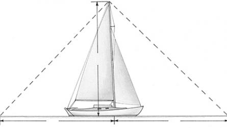
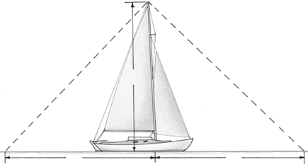
The Faraday cage, or “zone of protection” for a typical sloop.

Zone of protection for a large sailboat with a masthead more than 50’ above the water. The radii indicated are both 100’ for a mainmast height of 50′.
A lightning rod mounted at the highest point of a boat and connected to a ground system isn’t enough protection on its own. Not only a sailboat’s mast but also its rigging should be connected to the grounding system to provide a “zone of protection,” or “Faraday cage.” This phenomenon, recognized by its discoverer, the English scientist Michael Faraday (1791–1867) in 1836, protects areas inside this “cage” of conductive materials by redistributing electrical charges in response to an external static electrical field. On board a boat, this cage is formed by conductive materials related to the masts, and in order to function properly it should involve rigging elements such as shrouds and stays as well. A common error is to neglect the inclusion of such fittings as wire topping lifts or running backstays, which can conduct side flashes. For example, a charge from the outhaul at the end of the boom or a block for the running backstay may arc into the cockpit, where any crew member at the steering pedestal or a winch risks being struck by acting as a bridge to complete the circuit to ground. For a sailboat with a split rig, both masts, as well as the springstay, must be connected to the grounding system to extend the protection of the “cage.”

Lightning protection for a powerboat with its masthead no more than 50′ above the water. The outer dotted line represents the protected zone with a solid lightning rod extending the height of the lightning mast—note that it extends the Faraday cage aft well beyond the cockpit and transom. The inner dotted line represents the zone protected by using the lightning mast only.
Powerboats, meanwhile, pose their own challenges for lightning protection. Because they are low-profile, they are often considered to be low-risk targets for lightning. This assumption is true enough if the boat is at an anchorage surrounded by sailboats. Out on the water, however, one would still have the potential to be struck. In fact, noted accident reconstruction authority Robert Loeser states that “most all boaters killed by lightning are in open powerboats.” The obvious problem is that powerboats don’t have the convenience of tying a lightning ground system to a tall mast and a big metallic keel. The absence of a clear vertical ground path could contribute to side flashes, where the strike jumps in random horizontal fingers to large metal objects such as engines, tanks, or stoves. Loeser recommends installing a plug-in type of removable lightning rod forward of the steering console. The base of the rod holder should ground with a No. 4-gauge cable led directly to a grounding plate.
Specifics of a Lightning Protection System

A masthead lightning rod of copper, extending a minimum of 1′ above the masthead, with a copper strip to conduct a lightning charge down the mast via the sail track. To make the turn around the mast, the strip has to be bent back on itself to make a 90-degree bend, but its size helps to alleviate this problem. This rod doubles as burgee staff by being fitted with a wooden ring and a light halyard.
Any lightning protection system for a boat begins with a lightning rod (simply a pointed or rounded copper or aluminum terminal) at the masthead, sometimes called the “air terminal.” In a boat with an aluminum mast, the spar itself can serve as a conductor. Many wooden boats, however, have wooden masts, and these present a particular problem. The high resistance and moisture content of a wooden mast can cause it to split open if it is forced to become the conductor in a lightning strike. For a wooden mast, a separate conductor should be installed. Often, the metal sail track—if there is one—can be incorporated as the conductor if it is bonded not only to the masthead lightning rod but also to the ground connection. In any case, the main conductor from the spar must be the equivalent of No. 4-gauge wire. Secondary conductors, for example incorporating the shrouds, boom fittings, or other rigging components, should be No. 6 gauge wire or the equivalent.
Copper grounding straps for lightning protection are available commercially, or they can be fashioned from copper wiring or flashing. Copper prices are high, so cutting strips from standard 7″ solid copper flashing could be cost-effective if you need a lot of it. A disadvantage of strapping is that it can bend in only one direction, so sometimes to make a necessary bend it must be folded back on itself, making a 90-degree turn, the problems of which can be ameliorated by using a comparatively wide piece.
The most common mistakes in conductor installation are that the cable is undersized, or that it runs indirectly—like a standard 12-volt circuit. Because these conductors have to pass a surge of thousands of amps, the high resistance of thin wires with kinks in them could lead to the wires merely vaporizing during a strike. The sizes recommended here are minimums; bigger is always better (and don’t ask Mr. Lightning Bolt to hang a left and two rights on this merry way to ground).
In addition to the conductor on the mast, the other rigging components such as shrouds must be led to ground. For shrouds, the conductor should lead directly from the chainplates in a nearly vertical path to the grounding system. The connection at the chainplates is usually via the through-bolts holding them to the hull.
The final step in the lightning protection system is to lead the lightning charge conductors to ground. Often, the metallic ballast keel offers the most convenient way to ground the charge, the terminus for the down-conductors being ballast keel bolts. This installation takes advantage of the great mass of external ballast to dissipate the charge into the water. It also means that you’ll have to draw wires down into a wet bilge, which may raise concerns about stray current corrosion of metals; however, failing to install a lightning ground system for fear of stray current is like throwing the baby out with the bath water. The ground system itself doesn’t create the current problems—and failure to install the ground will not solve a preexisting electrical problem. (Wooden boats, according to the best modern authorities, should not have electrical bonding systems because bonded metals fittings in contact with wood can cause electrochemical deterioration of the wood itself. Regardless, for those boats that do have a bonding system, the lightning protection system should be entirely separate from the bonding system. Lightning grounds must never run horizontally and should never be connected to metal through-hull fittings such as seacocks.)

The foot of the sail track contacts copper strapping that carries the load downward. Copper strapping also bonds other rigging elements, in this case leading a charge from the metal sail track on the boom via the metal gooseneck fitting to the main down-conductor. This prevents dangerous side flashes from the boom. Sometimes, 90-degree bends like these are unavoidable, though the size of the strapping helps to alleviate this problem. The strapping along the mast continues downward past the mast partners to the foot of the mast.
For a boat without a ballast keel, the lightning protection system should ground to an installed grounding plate of at least 1 sq ft mounted below the waterline on the exterior of the hull. The electrical connection is made by connecting the copper strapping or wiring of the down-conductor to the through-bolts holding the plate to the planking.
A boat used on fresh water should have an even larger plate, since fresh water is less conductive than seawater. One other option for a ground plate, other than a simple square of copper, is an external grounding strip. The American Boat and Yacht Council standard E-4 details this installation, which Loeser has used on his own boat. The strip should be a minimum of 3/16″ x 3/4″ and 6′ in length. It is fastened forward and aft with two bolts at each end. The forward end should be positioned and grounded directly beneath the main conductor (below a maststep in a sailboat, for example). The bolts at the after end can serve as a direct and convenient ground point for the engine and backstay. The configuration of the strip provides more than six times the “edge area” of a conventional 1-sq-ft plate. The effective area of the strip could be increased by spacing it off the hull with washers, which may require adding intermediate bolts to hold the metal away from the hull.
Preventing Damage to Electronics
A great percentage of unprotected boats are struck at the VHF radio antennae, and even on a boat with an effective lightning protection system, it can be very difficult to prevent the antenna from being struck. The attached coaxial cable acts as one of the conductors to draw the strike into the boat, where it blows out not only the radio but other electronics. While the massive inductance generated from a direct strike will tend to blow out most sensitive circuit boards, there are some relatively inexpensive ways to help improve electronic survivability. A sloop’s VHF antenna is usually the boat’s highest point, so there is really no way to avoid drawing a strike to it. But with a split rig, the antenna can be mounted on the mizzen mast in hopes that the lightning rod installed on the mainmast will take the brunt of the strike.
Some experts recommend the installation of devices such as a lighting “spark gap” or a metal oxide varistor up at the loading coil of the antenna, but the success of these units is questionable. The spark gap represents relatively old technology and acts almost on the idea of a capacitor, where a certain voltage will jump the gap and pass on to ground. With the device located up at the source of the strike, there is a question of whether it can divert all the voltage down the ground wire and keep it out of the coax cable. Metal oxide varistors react far quicker than a spark gap but are themselves more sensitive to damage. None can handle the extreme loads of a lightning strike without shorting.
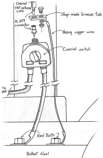
The primary conductor from the mast terminates at a keelbolt in a direct line with the maststep. Note that the shroud and secondary stay conductors also lead down to the keelbolt. Horizontal runs should be avoided. Right-angle turns should also be avoided, though they may be necessary with strapping, as shown—a problem that can be lessened by making the straps comparatively large. The masthead VHF coaxial cable, shown running fore-and-aft, is fitted with a gas-tube suppressor that makes contact with the primary down conductor. This fitting should pass a massive spike straight to ground, preventing it from reaching the cabin and the boat’s electrical system. A coaxial switch mounted on the mast can be quickly and safely turned to isolate the VHF radio, along with the rest of the boat’s electronics. If lightning strikes the masthead antenna, the switch diverts the charge to a keel bolt ground connection. A backup ground, using a shop-made bronze tab mounted between the fittings of a standard PL 259 coaxial connector, uses heavy copper wire to further increase grounding capacity.
One option is to install a gas-tube-type surge suppressor in the coax line at the base of the mast. The unit reacts instantaneously and is designed to withstand high-voltage spikes. It simply screws into the coax line, and it has a provision for accepting a grounding wire. The manufacturers recommend connecting the suppressor to the coax cable at least 3′ to 5′ before the cable reaches the radio. Ideally, the strike will pass through the suppressor and onward to ground, rather than to the electronics.
Another way of ensuring that the strike doesn’t destroy the electronics is simply to disconnect the antenna from the back of the radio. However, touching one hand to an antenna coax and the other to ground at the onset of an electrical storm is a very bad idea. A safer way to approach this matter would be to install a three-way coax antenna switch (available at ham-radio stores). This switch should be backed up by a substantial direct ground connection (see diagram). By turning the switch, the surge can be directed to ground instead of to the electronics.
One last gadget involves “prediction” rather than “prevention.” The device, called SkyScan, is an affordable handheld unit that reads and ranges radio nose created by lightning activity from up to 40 miles away. It’s another trickle-down item—the unit was originally developed for ball fields and golf courses. Calibrated for closing ranges, it also gives an idea of a storm’s severity. By indicating an oncoming storm from over the horizon, the unit could provide a valuable “duck and cover” function, allowing you to anchor, leave the boat, and avoid the danger of an electrical storm in the first place.
For further information, see WoodenBoat Nos. 215 and 136.
Jonathan Klopman is a certified NAMS mariner surveyor and specializes in wooden boats. His office is in Marblehead, Massachusetts, and he works throughout New England.
