Introduction
Scarf joints have been used in wooden-boat construction for centuries. There are many variations on the basic scarf joint; these include feathered, tabbed, and hooked scarfs. And there are many applications for them, from joining together planks to making up full-length mast staves from shorter pieces.
With advances in structural engineering leading to progressively lighter boats—coupled with significant progress in adhesives—the mechanical properties and strength of scarf joints compared to solid timber must be fully understood.
Scarfs are defined by the length of their slopes in relation to the thickness of the pieces being joined together; this relationship is described as a simple ratio—for example, a 4:1 scarf in 1″-thick piece would have a slope length of 4″, measured parallel to the timber's surface. Traditionally, scarf ratios have been driven by the location of the scarf: 4:1 for planks, 6:1 (possibly 8:1) for keels, and 12:1 for spars. The old Lloyd’s rules state that plank scarfs should not have a length-to-thickness ratio less than 4:1, adjacent planks shall not have scarfs within 1.2m of each other (about 4′), and a minimum of three complete planks shall separate scarfs in the same transverse plane. In addition, keel scarfs shall have a ratio no less than 6:1, and the keel and hog scarfs should be spaced by at least 1.5m (about 5′), while being clear of engine bedlogs and maststeps. In those historical instances, it can be deduced that an increased scarf ratio leads to greater strength but that scarfs still represent weak spots that should be spaced out and not subjected to high localized loads. Richard Birmingham, in his book Boat Building Techniques, states that the efficiency of scarfs ranges from 65 percent of the strength of solid timber for a 4:1 ratio and up to 95 percent for a 20:1 ratio.
Structural Testing
In order to provide a detailed analysis of how scarf ratios affect the strength of boat timbers, destructive structural testing was undertaken on European oak (Quercus spp, having a density no less than 690kg.m3 at 12% moisture content) samples joined together with feathered scarfs glued with epoxy. In order to faithfully replicate a typical boatyard scenario, the samples were manufactured from different quartersawn boards, never joining pieces from the same board. Ratios of 4:1, 8:1, 12:1, 16:1, and 20:1 were tested, comparing all of them to solid samples. The aim was to ascertain the relative strengths of the various scarf ratios, for the wood species and adhesive ultilized in this instance, both of which are prominent in the boatbuilding industry, to provide designers and builders with relevant and reliable information. The regulatory default values we also evaluated.
To assess the strength and mechanical properties of samples, a number of destructive tests can be employed; for timber, four-point bending is preferred, and it allows one to establish the ultimate flexural strength (sometimes referred to as modulus of rupture) and elastic modulus (the material’s resistance to being deformed; also known as Young’s modulus). In four-point bending tests, the sample is simply supported at each extremity, while the load is applied evenly at two locations equidistant from the center, as depicted in Figure 1. Structural experiments use a very precise methodology, imposed by international standards to ensure the reliability, accuracy, and repeatability of the results obtained. In this instance, the British BS EN 408 standard applies; it specifies sample sizes, load location, and loading rate, as well as how to characterize mechanical properties. In these experiments, seven samples were tested in each case (the standard requires five).
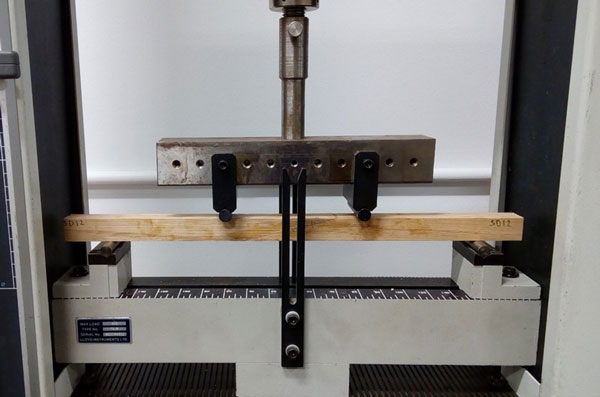
Figure 1: Four-Point bending test undertaken at Solent University (UK) under the BS EN 408.
As the load is applied, the sample will deflect a measured distance; a time-lapse of this is presented in Figure 2. Graphically, this is represented in a load-versus-deflection curve, analogous to a stress-versus-strain curve. Stress is the ratio of the force over the cross-sectional area; strain is a measurement of the deformation. Each material will have a characteristic stress/strain curve that allows one to comprehend and quantify its mechanical behavior and properties. The slope of the curve, which is equal to the stress divided by the strain, yields the modulus of elasticity. Furthermore, the stress/strain curve enables one to identify when the ultimate strength of a material is reached—i.e. the maximum amount of stress that can be withstood, before fracture occurs.
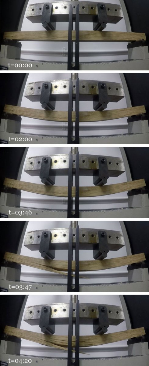
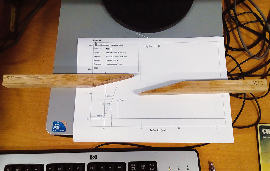
Figure 2: Time lapse of a solid sample being loaded to failure.
Qualitative Results
From the experimental testing, typical load-versus-deflection curves for the various scarf ratios compared to solid timber were obtained (see Figure 3), yielding three main findings.
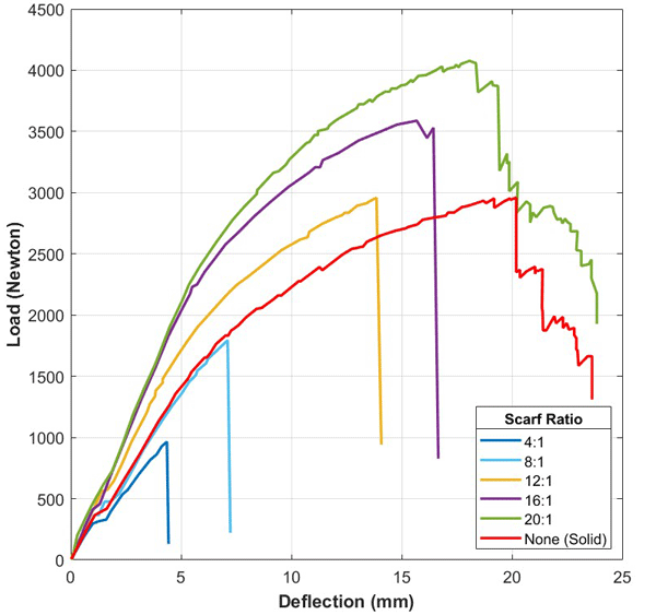
Figure 3: Typical load versus deflection plots for the range of samples tested.
First, the results clearly demonstrate that the small scarf ratios (4:1 and 8:1) have a lesser resistance compared to solid timber, whereas the opposite is true for the higher ratios (12:1, 16:1, 20:1). Practically, this means that higher scarf ratios have a higher modulus of elasticity than the solid timber and will be able to carry more load for a given deflection.
The second important result is that solid timber withstands the most deflection before ultimate failure; in other words, despite not carrying as much load as a high-ratio scarf, solid timber is able to deflect much farther than scarfed samples.
Finally, there is an interesting shift in the failure mechanisms, shown in the fracture behavior. For ratios ranging from 4:1 to 16:1, the fracture is sudden and abrupt, with no strength left. In these cases, it was the epoxy bond that failed. Conversely, solid timber and the 20:1 scarf do retain some strength, as it is the timber and not the adhesive that failed in those instances. The two failure modes are presented in Figure 4. This proved true for all samples tested with the exception of a single 16:1 ratio where a combination of timber and glue failure (attributed to a weak spot in the timber) was noticed.
It is to be noted that these findings will be affected by the adhesive employed, and could vary for different glues.
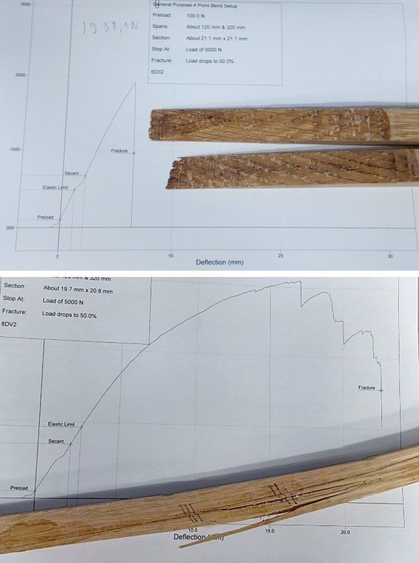
Figure 4: comparison of glue (top) and timber (bottom) failure, the former leading to complete rupture of the sample.
Quantitative Results
Among the many mechanical properties that can be ascertained from this experiment, the two of primary importance here are the modulus of elasticity and ultimate flexural stress, respectively labeled in most publications and regulations as E// and σuf //, where the subscript ‘//’ specifies that those properties are given parallel to the grain.
In the absence of mechanical testing, default values would be provided by the relevant rules and regulations. For small-craft scantlings, Annex F of the Hull Construction and Scantlings standard published by the International Standards Organization (ISO 12215–5) specifies the default mechanical properties of typical wood species. For atypical species, the mechanical properties can be derived as a direct function of the density of the wood, because density has a significant impact on mechanical properties. Hence, the ultimate flexural strength and modulus of elasticity of a hardwood of density ρ (kg.m-3) can be approximated as:
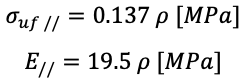
The equations are slightly adjusted for softwood, and respectively given as:
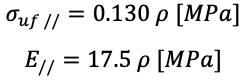
The unit of Mega Pascal (MPa), where 1 MPa ≈ 145 psi (pound-force per square inch), is used to represent the amount of load that can be carried over an area.
Unfortunately, regulatory bodies do not account for the presence of scarf joints or their ratios. Both values ascertained in the study are of paramount importance. For a strength-driven design, where the primary concern is to ensure stresses remain below an acceptable level, the ultimate flexural strength will be utilized. Note that, in this instance, a safety factor would be employed to ensure added reliability, and to ensure that the material does not suffer from permanent deformation under normal loading.
As a minimum requirement, the ISO 12215–5 imposes a safety factor of 2 on the ultimate flexural strength, which leads to the design stress value,  ultimately employed is the calculation of thickness of panels, and section modulus for stiffeners. On the other hand, the modulus of elasticity comes into play for stiffness-driven designs, where the primary intent is to limit deflection to a comfortable level. In structural testing, the final retained values for the mechanical properties are typically the lesser of either 90 percent of the average across all samples, or the average value achieved to which two standard deviations are subtracted (where the standard deviation measures differences among samples compared to the mean), thus accounting for the scatter in the data. In all cases, the average minus two standard deviations proved to be the most pessimistic case, and thus was retained. Table 1 below presents the average variation in two principal quantities of interest here, and demonstrates the conclusiveness of the results obtained.
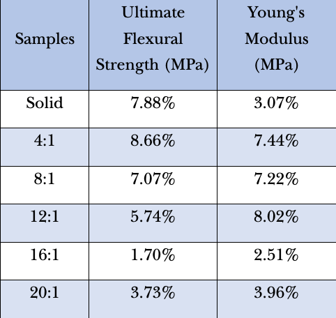
Table 1: Variance in the quantitative results for each sample group and mechanical property.
The flexural strength and modulus of elasticity can then be plotted against the increasing scarf ratios of the samples, and compared to standard values given by structural regulations from ISO and the American Bureau of Shipping (ABS), as well as solid timber. The experimental results are also compared to the flexural-strength rule of thumb in Birmingham’s book.
The results are presented in Figure 5 as scarf efficiency, where 100 percent represents the strengths of the solid timber as determined experimentally.
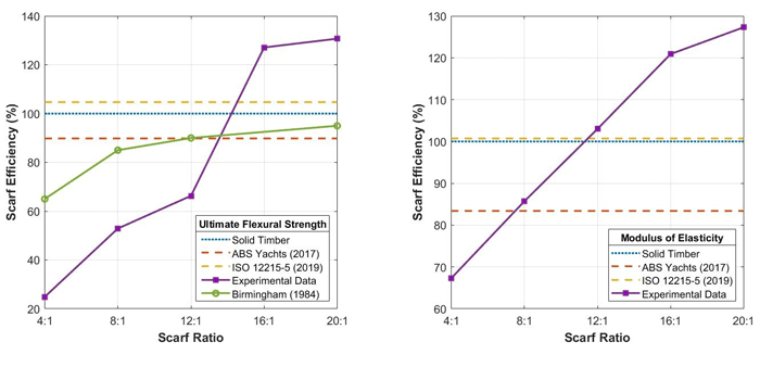
Figure 5: Scarf efficiency in ultimate flexural strength and modulus of elasticity compared to typical regulatory values.
The results reveal striking differences between the experimental data and both solid timber and the previously existing information. This implies that greater care should be taken in the design of structural components with a low scarf ratio, and thus a higher safety factor should be used. Conversely, the higher end of scarf ratios showed a significant improvement in mechanical properties, which could therefore be strategically utilized, particularly for weight-critical components, thus justifying the requirement for high ratios for spars.
The default properties provided by rules and regulations are listed in Table 2. There is a large difference in the actual values, with ABS specifying more pessimistic mechanical properties and imposing a larger safety factor than the ISO standard. The latter also proved to be more in line with the results for solid timber.
It is, of course, vital to point out that the mechanical properties of wood can vary greatly and be affected by a wide range of parameters, including density, moisture content, grain orientation and straightness, defects, and so on, eventually leading to higher safety factors when designing wooden boats. The safety factor adopted is also influenced by the thickness of wood: large sections carry greater uncertainty as to grain orientation and the presence of defects, which means they generally require an increased safety factor. On the other hand, it is easy to spot any defect in thin pieces of wood. As a result, laminated components made of thin veneers generally permit reduced safety margins, allowing lighter and stronger structures.
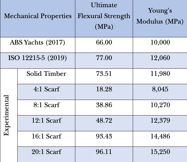
Table 2: Quantitative results of the experimental testing compared to default regulatory values.
Conclusions
The examples here demonstrate that, in considering either the ABS or ISO default ultimate flexural strength and inherent factor of safety, the design stress would have been over-estimated and thus would not have prevented failure of the 4:1 scarf ratio. Structural testing is a time-consuming and expensive approach. It is hoped the results provided in this article offer an efficient alternative and will allow designers and builders to adjust safety margins where necessary or help justify the need for an increased scarf ratio. Finally, the fact that these findings are specific to the timber species and adhesive tested here should be reiterated. While qualitative similarities can be expected from different species and glues, quantitative results will require further research.
Jean-Baptiste R.G. Souppez is a senior lecturer in yacht design and composite engineering at Solent University in England. He is also a visiting professor and research supervisor at University of Liege, Belgium, and the U.K. principal expert in small-craft structures for the British Standards Institution.
Contact: jean-baptiste.souppez@solent.ac.uk
A refined understanding of the effects of slope