Yacht Design Terminology
Our profile of yacht designer Paul Gartside in WB No. 230 included a number of design terms that space and style restrictions kept us from defining in the article. For those readers seeking a deeper understanding of the elements of design, here are the definitions of those terms—along with a few additional ones that were not listed in the article. — Robin Jettinghoff, Assistant Editor
Area of Wetted Surface: The hull’s surface below the waterline; what you cover with bottom paint. Besides determining the amount of bottom paint to buy, the area of wetted surface determines how much friction there is between the boat and the water. Minimize the wetted surface, and you maximize the speed. A boat flying on foil goes faster because it has none of its hull in the water; the only wetted surface is that of the foil.
Beam: The width of the hull measured perpendicular to the centerline of the hull. The beam is a significant factor in both carrying capacity and stability.
Maximum Beam (B or BMAX): On a hull that flares toward the sheer, the maximum beam will be at the sheerline. On a hull with tumblehome, the maximum beam will be below the sheer. On a trimaran hull, the maximum beam of the main hull and the beam of the three hulls together are significantly different; the former gives a sense of the boat’s capacity, the latter, of its stability. The maximum beam is important when finding a slip in a marina, and is often a factor in racing rules.
Beam of Waterline (BWL): The maximum beam of the hull at the designed waterline. This is a factor in determining its displacement and prismatic coefficient.
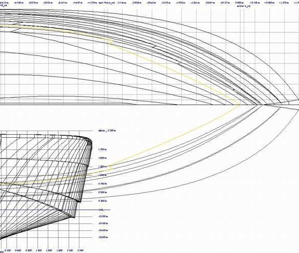
Buttock Lines: In a set of lines plans, lines showing the underwater shape of the hull. In the profile view, they are seen as curved lines parallel to the centerline of the hull, spaced an even distance apart, showing how the shape of the hull changes moving outward from the centerline. In the plan view, which also shows the waterlines as curves, the buttock lines are at equal intervals and parallel to the longitudinal centerline of the hull. In the section view (seen from dead ahead or dead astern), they are vertical lines and parallel to the centerline of the hull.
Center of Buoyancy (CB): The center of volume of the underwater part of the hull, below the DWL. The water pushes on the hull with an upward force, centered on this point, keeping the hull afloat. As the hull moves through the water, the underwater shape changes and the CB moves, but it must stay in the same vertical line as the center of gravity or the hull will go out of trim. Designers need to know the longitudinal center of buoyancy (LCB) when the hull is at rest, so they can locate weights fore and aft of that point in such a way that keeps the hull in trim.
Center of Effort (CE): The geometric center of the sail area. A designer finds the CE of a sail by drawing a line from the midpoint of the luff of the sail to its clew. Then he draws a line from midpoint of the foot of the sail to the head of the sail. Where these lines cross is the center of effort of that sail.
To find the CE for the sail area of a main and jib, the designer computes the area and the location of the CE for the main and jib individually, then draws a line connecting their CEs. The CE of the two sails is on this line. Its location is in proportion to the areas of the two sails. For example, if the mainsail is 250 sq ft, and the jib is 100 sq ft, the jib is 100/250 or two-fifths of the area of the main. The CE would be two-fifths of the way along the line going from the main’s CE to the jib’s.
If the CE is too far aft of the CLR, the boat will have weather helm; if it is too far forward, it will have a lee helm.
Center of Gravity (CG): The weight of the vessel in the water creates a downward force that is concentrated at the center of gravity. The CG and center of buoyancy (CB) are opposing forces.
Center of Lateral Resistance (also called Center of Lateral Plane; CLR or CLP): The geometric center of the profile of the underwater part of the hull. This is a center of balance. If you try to balance something on the tip of your finger, you move the object back and forth incrementally on your finger until it balances. Similarly, if an underwater force on the side of a hull is trying to push the hull at right angles to the force, and the force is the too far forward, the force will push the boat’s bow farther than it will the stern. If the force is too far aft, then the stern will be pushed farther than the bow. When the force is pushing on the balance point between these possibilities, the hull moves at right angles to the force. This point is the center of lateral resistance. The force of the wind is concentrated on the center of effort. Its location in relation to the CLR will determine if a boat has weather or lee helm.
A designer can find the CLR of a hull by tracing the underwater profile onto a piece of stiff paper. Then he cuts out this out and balances it on the edge of a ruler. Next he marks this line of balance, and rotates the hull profile, balances it again, and draws a second line showing where it balanced. The intersection point of these lines is the CLP.
Construction Method: The method of construction and materials used in building a boat. Both greatly affect the cost of a boat. One of the reasons fiberglass hulls became so popular was that they could be mass-produced more cheaply than wooden hulls. Boats have been built from wood, plywood, fiberglass, metal, combinations of composite materials, and concrete. Each has different properties in cost, ease of construction, strength, ease of repair, and accessibility of materials. The designer and owner together will discuss the pros and cons of the different methods to find the one that best fits the owner’s needs.
Deadrise Angle: The angle between the bottom of the hull and a horizontal plane drawn out from the hull’s centerline, looking at the hull sections. A steeper deadrise angle will mean the hull sharpens and narrows as it gets deeper, while a smaller angle means the hull bottom is flatter.
Displacement (Δ): The underwater volume of a boat is equal to the volume of water it displaces. Underwater volume is expressed in cubic feet or meters; displacement is the weight of the water displaced, and is expressed in pounds, tons, or tonnes. A boat that has an underwater volume of 125 cubic feet displaces 125 cubic feet of water. This displaced water weighs 64 lbs per cu ft (in salt water, about 62.5 lbs/cu ft in fresh water); 125 x 64 = 8,000 lbs. Since the weight of that displaced water is equal to the weight of the entire boat, 8,000 lbs is the boat’s displacement.
A common demonstration of displacement can be done with a model boat, a bowl big enough to hold the boat, a shallow pan, a small scale, and enough water to fill the bowl. Put the bowl in the shallow pan, then fill the bowl with water up to the brim. Gently float the model in the water, and some of the water will overflow from the bowl into the pan. Weigh the water in the pan and weigh the model, and you will see they are same weight. The model weighs exactly the same as the water that it displaced.
Displacement/Length Ratio (Δ/L): The ratio between the LWL and the boat’s displacement. The formula is the displacement divided by 1/100th of the length of the LWL cubed, or Δ/.01LWL3, where the Δ is in tonnes (1 tonne = 2,240 lbs).
Draft: The maximum measurement from the designed waterline to the bottom of the hull. A boat with a centerboard will have two drafts. A sailing dinghy, such as Joel White’s Haven 12-1/2, will draw 18″ with the centerboard up, and 3′4″ with it down. Shallow-draft hulls, such as CARIB II (see WB No. 228), will often have centerboards so they can travel more easily in shallow water, such as that found in the Florida Keys and the Bahamas.Freeboard: The measurement from the designed waterline to the sheerline. This is most obviously demonstrated in a small dinghy with more than one adult aboard. As the weight inboard increases, the freeboard decreases. The freeboard is usually highest at the bow and lowest somewhere near amidships. The minimum freeboard is the number of most concern.
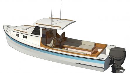
Interior Amenities: Cabin comforts and accommodations. To spend more than a few hours aboard a boat, people will need to consider their needs for food, water, rest, lighting, and elimination of wastes. Amenities aboard a boat might be as simple as a berth on the floor of the cockpit, a bucket, a candle lantern, and a portable stove. A weekender might have a small Coleman stove, a couple of battery-operated lamps, a V-berth, and Porta-Potti.
Offshore cruisers want the means for dealing with these fundamental human needs to be as convenient as they are at home. Lighting will need wiring and some source of power—perhaps a solar cell or generator. An efficient galley needs a sink, which requires a tank for fresh water, a hose from the tank to tap, and a drainpipe to deal with the wastewater. A galley stove needs some source of heat, requiring another tank and more hose. A head requires a sink with tank, hose, and drain, as well as a toilet with hoses for water in and water out, and a holding tank for the wastes. All of these systems add to the cost and complication of a design.
Length: The length of a hull as measured down its centerline. There are at least four descriptions of the length of a boat (see below); the length in question will depend upon what you are looking for. A marina manager wants to know the maximum length of the boat, so it can be seated in a slip. Racing rules are often concerned with the length of the load waterline. Designers working around these rules have led to some extreme hull forms in an effort to beat the rule constraints.
Length Overall (LOA; sometimes Length of Hull): The overall length of the hull. In a dinghy, this is relatively clear; with the boat out of the water, one can hold a tape measure down the centerline of the hull from the after side of the top of the transom to the forward edge of the stem. The measurement gets more complicated in a canoe with tumblehome stems, one whose stems curve inward as they rise from the waterline toward the top of the hull. For most motorboats and rowboats, the overall length is pretty evident. Rudders, anchor rollers, or other hull extensions are not included in this measurement.
Length on Deck (LOD): The length along the centerline of the deck, measured from its tip at the bow, the intersection of the deck line with the profile bow line, to the point where the deck meets the transom. This provides a better tool for estimating a boat’s carrying capacity than does overall length.
Load Waterline Length (LWL): The length of the hull measured at the waterline. When the designer draws the boat on the plans, he or she computes a plane on the hull where the boat will float in its expected operating condition. The actual waterline will vary from this in use. A fishing boat on its way out to the fishing grounds will float higher in the water than when it heads home fully loaded with fish. A cruising boat out for a weekend adventure will not have as much gear aboard as one fully loaded for an ocean passage. The designed waterline should lie between these two maximums.
The designed waterline (DWL) and load waterline (LWL) are usually in the same plane on the hull. The waterline length is the critical factor in determining the maximum speed of a displacement hull. Sailing boats with long overhangs at the bow and stern will increase their waterline length as they heel over while sailing; this increases their maximum speed potential.
A design will have several lines parallel to the LWL at set distances apart. These lines, also called waterlines, define the shape of the hull in plan view on the drawing board.
Sparred Length: The maximum reach from the tip of the bowsprit to the aftermost point of the boom. According the racing rules in place for the 1903 AMERICA’s Cup race, Nathanael Herreshoff’s RELIANCE was required to have a waterline length of no more than 90′. Herreshoff built her to be an extreme hull that still met the parameters required by the racing rules. Her measured waterline length was 90′, her hull length was 144′, and her sparred length was 201′.
Length-to-Beam Ratio (L/B): The ratio between the hull length and the maximum beam. This is a factor in the boat’s stability and speed. A sculling hull used by eight rowers has a length of about 50′ with a beam of about 2′, giving an L/B of 25. While a Cape Cod catboat might have a length of 22′, and a beam of 8′ giving an L/B of 2.75. As the L/B increases, the boat’s speed should also increase.
Offsets: A table of measurements taken vertically and horizontally that establish the shapes of the hull’s frames. The vertical measurements, or heights, are taken from a baseline established by the designer, either the DWL or a horizontal line parallel to the DWL below the boat’s profile as drawn on the plans. The heights are measured at equal intervals measured from the centerline of the hull. The lines joining the height measurements are called buttock lines. The horizontal measurements, or half-breadths, are taken from the boat’s longitudinal centerline. These are measured at equal intervals above and below the boat’s DWL. The lines joining the half-breadth measurements are called waterlines. The stations are measured at equal intervals from a forward perpendicular established by the designer.
Outside Ballast: Weight attached outside the main hull, as in a ballast keel, that lowers the CG and counterbalances the forces on the sails to keep the boat upright. A keel also provides lateral resistance to help prevent the sails from pushing the boat sideways in the water.
Prismatic Coefficient (Cp): The percentage of volume that a hull’s shape has when compared to a prism as long as the designed waterline, and the shape of the hull below the waterline at the largest hull section. For example, if the LWL was 25’, and the underwater cross-sectional area of the largest section was 12 sq ft, then the volume of that shape is 25 x 12 = 300 cu ft. But a boat does not have the same sectional shape all the way along its length; the actual volume of the hull is carved from this shape.
If you had a wood block in this shape, and carved the wood away until you only had the shape of the hull left, the volume of the material remaining is a percentage of the total volume of the block. This percentage is the prismatic coefficient. If you have 125 cu ft left, the boat has an underwater volume of 125 cubic feet; divide 125 into 300, and 125 is 42 percent of 300, so the Cp is .42. If you have 189 cu ft of underwater volume left, the Cp is 189 ÷ 300 = .63.
A lower Cp means the boat’s volume is concentrated toward the middle of the boat. Hulls with a higher Cp move some of that volume toward the ends, increasing their speed and making them less inclined to pitch. If this coefficient is too high, wave drag increases, slowing the hull down. Most designers have a prismatic coefficient in mind for the hull they are designing.
Profile: The shape of the centerline of the hull as seen from the side. Most plans show the boat facing right so the profile is what you see from the right side. The profile is generally bounded on top by the sheerline, at the bow by the curve of the stem, underwater by the keel, and aft by the transom, with buttock lines showing the shape of the hull from the centerline outward.
Propulsion: The method by which a boat moves through the water. If a designer is designing a powerboat, he or she must know the weight of the boat to determine the correct engine horsepower and propeller to drive the boat most effectively. A designer also recognizes that engines are heavy and must be placed in a boat so they don’t upset the boat’s trim. Also the engine’s controls must be connected to some kind of helm station—providing the helmsman with a throttle, a gearshift, and a steering wheel, stick, or tiller. The designer of a sailboat must cope with another force acting upon the boat: wind. The designer must determine how much sail area is needed to move the boat through the water, the amount of ballast necessary to counteract the force on the sails, and the location of the sails and rig to keep the boat in balance.
Righting Moment: The restoring force by which a hull resists heeling, created by the ballast keel and the form stability of the hull.
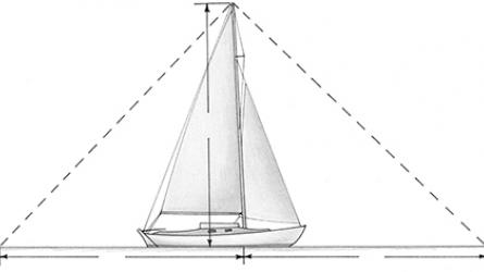
Sail Area (SA): The surface area of sails needed to drive the boat. The designer draws each sail on the plans, then divides the sails into triangles. Then he applies the familiar formula for determining the area of a triangle (area = ½ base x height or ½ bh) and computes the area of each triangle in each sail, then adds them up to get the total sail area. Boats with multiple headsails—like staysails, genoas, or spinnakers—will have different sail areas depending on what sails are flying. A designer determines the total sail area needed to drive a boat by looking at comparable designs. The published sail area of a design is usually the sum of the mainsail area and the foretriangle area, which is the area bounded by the mast, headstay, and deck.
Sections: The hull’s shape on vertical planes cut perpendicular to the boat’s centerline. A designer shows three views of the hull on the drawing board: its profile, or appearance from the side; its plan view, or appearance from the top or bottom; and its sections, or appearance from the bow and stern. All the lines defining the hull appear in all three views; but in each view, two of the line types are straight lines at right angles to each other, and the third type is curved. The hull sections show how the curve of the hull changes as it moves fore and aft.
Sheer: The curve along the top edge of the hull’s side, as seen on the profile view. A sheerline often sweeps downward from the bow toward somewhere around amidships, then sweeps up again as it heads toward the transom. Some boats have reverse sheers where the highest point is not at the bow but closer to amidships.
Speed-to-Length Ratio (S/L): A dimensionless ratio that indicates a hull’s hydrodynamic limitations of speed. A boat creates a bow wave as it moves through the water. As the boat’s speed increases, the wave gets bigger and creates more resistance for the hull to move through. A planing hull, with a typical S/L of 2.5 or so, can get up on plane and move over this wave, minimizing the resistance and letting the boat go faster. A displacement hull is too heavy to get over this wave. For a displacement hull, its limit of speed, or hull speed, is a Speed-to-Length Ratio of 1.34. For a displacement hull, its maximum speed is limited by its length. The formula for the S/L is the boat’s maximum speed divided by the square root of its length. In numbers, this looks like V/√L. So a 36’ cruising sailboat with a S/L of 1.34 has a maximum speed of 1.34 = V/√36. The square root of 36 is 6, so this formula now reads 1.34 = V/6, or multiplying both sides by 6 gives 1.34 x 6 = V, and V = 8.04 knots.
Stem: The forward part of the profile of the hull. The stem timber forms the forwardmost part of the hull, reaching from below the waterline up to the sheerline, providing a place for the planks to land in the hull’s construction. The sharp bend in the stem, usually just at the waterline, is called the forefoot. The angle of the stem to the water, and the angle of the planks to the stem, is a factor in whether a hull cuts through waves or slaps the top of them.
Transom: The after part of the profile of the hull. The transom spans between the hull sides at the aft end of the hull. It may have a sharp rake as on a Friendship sloop, or be nearly vertical as on some runabouts. Double-enders have no transom at all. Some commuter boats of the last century, such as APHRODITE, have a curving reverse transom, where the line of the deck curves over gracefully into the hull.
Underwater Volume: The measurement of the amount of the hull under the water in cubic feet or meters. The underwater volume and the boat’s displacement are two measurements of the same thing. The volume is measured in cubic feet or cubic meters, and the displacement is measured in pounds, kilograms, tons, or tonnes. See Displacement also.
Waterline: The hull’s shape on horizontal planes cut perpendicular to the boat’s centerline. A boat lying in the water floats with some percentage of the hull above the water and the remainder of the hull below the water. The waterline established by the designer is the plane that divides these two parts of the hull and is called the designed waterline, or DWL. The amount of hull within the water is a factor in determining the boat’s displacement, prismatic coefficient, and stability. The waterline of a small boat will shift when the crew changes position aboard. The waterline plane of a sailing monohull changes its shape significantly as the hull heels. People will often apply bottom paint to the load waterline and add a thin stripe (called a boottop) of contrasting paint just above it. The area of the hull above the waterline is called the topsides.
Weight: The weight of a boat. As with length, weight can depend on the situation in which you weigh the hull. The hull weight is the weight of the hull itself with nothing in it. Dinghies and skiffs often have little gear in them other than a pair of oars, so the hull weight is an accurate measure of their weight. If you add a motor to a small boat, then it weighs more, with most of the weight now at the stern. If you add passengers, they should be placed to balance the boat’s trim, so she will move more easily through the water.
For bigger boats, the hull holds water and fuel tanks, a deck, spars and sails, and interior furniture such as berths and a galley. When designing a boat, the designer places these items so that the boat stays level—much as you balance the crew of a dinghy as you carry them from dock to mooring. The designer also factors the weight of the crew into the design. Indeed, sailors count on the weight and placement of the crew to counter the forces of the wind on the sails. The weight of a boat and its displacement are the same thing.